ATTiny85 First Sketch
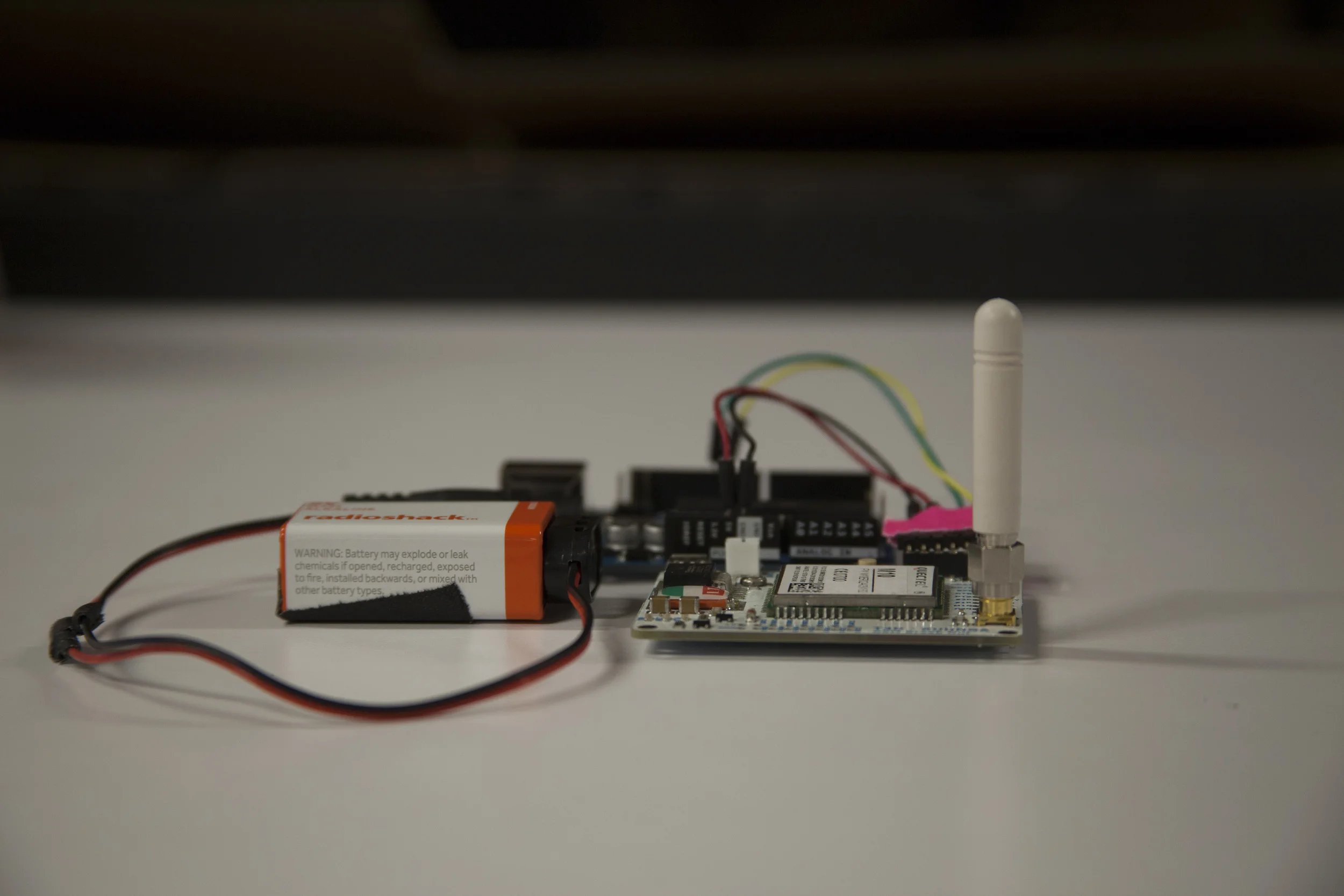
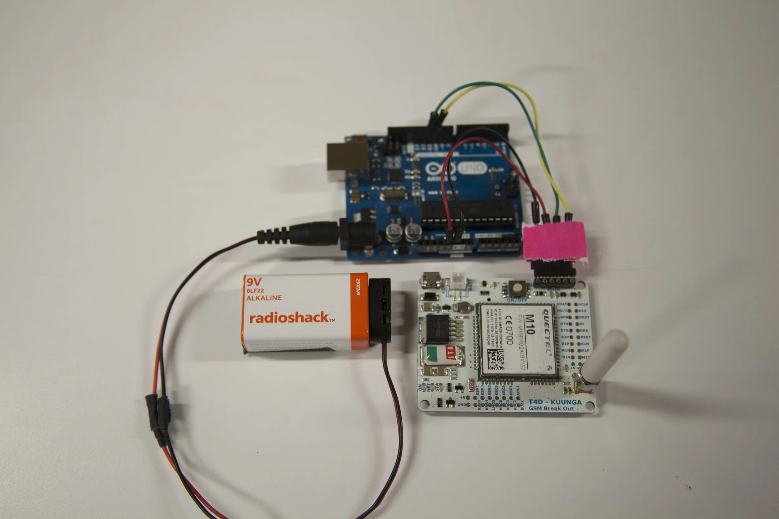
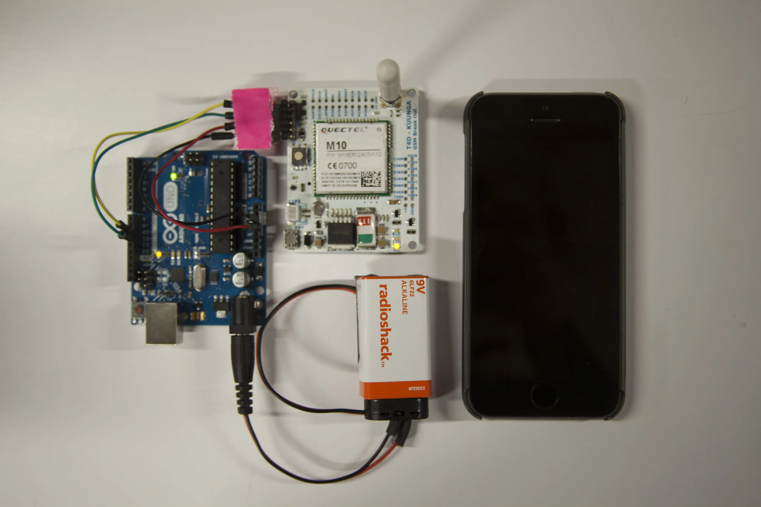
First successful try with ATTiny85, programmed through an Arduino UNO. Followed instructions found here
First successful try with ATTiny85, programmed through an Arduino UNO. Followed instructions found here
What could be a way to log ITP's entrance and see the difference between the elevators' use and the stairs'? Through a solar powered DIY Arduino, we decided to visualize this data (and store it in a .csv table) in the screen between the elevators at ITP's entrance.

After creating a DIY Arduino that could be powered through solar energy, by following Kina's tutorial we were able to set a basic solar rig that would charge the 3.7V and 1200 mA LiPo battery. We connected the solar panels in series and ended up with an open circuit voltage of 13V. Our current readings however, were of 4 mA.
We hooked the Arduino data to a Processing sketch that would overwrite the table data of a .csv file every second. All of the code can be found in this link.

How can a fabricated object have an interactive life? The M-Code Box is a manifestation of words translated into a tangible morse code percussion. You can find the code here and what's needed to create one M-Code Box is an Arduino UNO, a Solenoid Motor (external power source, simple circuit) and a laptop with Processing.
There are two paths to take this project further. One is to have an interpreter component, recording its sounds and re-encoding them into words, like conversation triggers. The second is to start thinking on musical compositions by multiplying and varying this box in materials and dimensions.
This project came upon assembling two previous projects, the Box Fab exploration of live hinges and the Morse Code Translator that translates typed text into physical pulses.
For our GSM class final, partnered with Clara and Karthik we created a Geo-Fence hooked to an Arduino Uno.
If you're receiving garble when reading the incoming data from the GSM through Arduino, you should check whether both boards are working at the same baudrate (9600). To change the GSM board –Quectel 10M– baudrate through an FTDI adaptor and CoolTerm:
Now plug the GSM Board to the chosen Software Serial PINS (10 and 11) and change the Fence center-point (homeLat and homeLon) the size –radius– of the fence in KMs (thresholdDistance) and the phone is going to be controlled from (phoneNumber), UPLOAD and run the SERIAL MONITOR. The code can be found in this Github Repo. Enjoy
The hardware used for this project was an Arduino UNO and one of Benedetta's custom GSM Boards with enabled GPS. This setup could work for potentially stand-alone purposes, however is advised to make sure beforehand that the power source has enough Watts to run the setup for the sought time.


A simple snippet to make an LED light up when receiving a SMS, with one of Bennedetta's GSM Shields
Lighting the LED pin 13 in the Arduino board. After several failed attempts of writing from Arduino Serial Monitor, we decided to do it through Coolterm.
This is the code:
#include <SoftwareSerial.h>

SoftwareSerial mySerial(2, 3);
char inChar = 0;
char message[] = "que pasa HUMBA!";

void setup()
{
  Serial.begin(9600);
  Serial.println("Hello Debug Terminal!");
  // set the data rate for the SoftwareSerial port
  mySerial.begin(9600);

  pinMode(13, OUTPUT);

//
//  //Turn off echo from GSM
//  mySerial.print("ATE0");
//  mySerial.print("\r");
//  delay(300);
//
//  //Set the module to text mode
//  mySerial.print("AT+CMGF=1");
//  mySerial.print("\r");
//  delay(500);
//
//  //Send the following SMS to the following phone number
//  mySerial.write("AT+CMGS=\"");
//  // CHANGE THIS NUMBER! CHANGE THIS NUMBER! CHANGE THIS NUMBER!
//  // 129 for domestic #s, 145 if with + in front of #
//  mySerial.write("6313180614\",129");
//  mySerial.write("\r");
//  delay(300);
//  // TYPE THE BODY OF THE TEXT HERE! 160 CHAR MAX!
//  mySerial.write(message);
//  // Special character to tell the module to send the message
//  mySerial.write(0x1A);
//  delay(500);
}

void loop() // run over and over
{
  if (mySerial.available()){
    inChar = mySerial.read();
    Serial.write(inChar);
    digitalWrite(13, HIGH);
    delay(20);
    digitalWrite(13, LOW);
    }

  if (Serial.available()>0){
    mySerial.write(Serial.read());
  }
}
Time's running out! Will your Concentration drive the Needle fast enough? Through the EEG consumer electronic Mindwave, visualize how your concentration level drives the speed of the Needle's arm and pops the balloon, maybe!

Second UI Exploration
I designed, coded and fabricated the entire experience as an excuse to explore how people approach interfaces for the first time and imagine how things could or should be used.
The current UI focuses on the experience's challenge: 5 seconds to pop the balloon. The previous UI focused more on visually communicating the concentration signal (from now on called ATTENTION SIGNAL)
This is why there's prominence on the timer's dimension, location and color. The timer is bigger than the Attention signal and The Needle's digital representation. In addition this is why the timer is positioned at the left so people will read it first. Even though Attention signal is visually represented the concurrent question that emerged in NYC Media Lab's "The Future of Interfaces" and ITP's "Winter Show" was: what should I think of?
What drives the needle is the intensity of the concentration or overall electrical brain activity, which can be achieved through different ways, such as solving basic math problems for example –a recurrent successful on-site exercise–. More importantly, this question might be pointing to an underlying lack of feedback from the physical devise itself, a more revealing question would be: How could feedback in BCIs be better? Another reflection upon this interactive experience was, what would happen if this playful challenge was addressed differently by moving The Needle only when exceeding a certain Attention threshold?
This installation pursues playful collaboration. By placing the modules through arbitrary configurations the idea behind this collective experience is to create scenarios where people can collaboratively create infinite layouts that generate perceivable chain reactions. The way to trigger the installation is through a playful gesture similar to bocce where spheres can ignite the layout anywhere in the installation.
After an apparent success –context-specific– and consequent failure –altered context– the project turned onto a functional alternative. The next process better illustrates it.
These images show the initial thought out circuit that included a working sound triggered by a –static– threshold. We also experimented with Adafruit's Trinket aiming towards circuit simplification, cost-effectiveness and miniaturization. This shrunk micro controller is composed by an ATTiny85 nicely breadboarded and boot-loaded. In the beginning we were able to upload digital output sequences to drive the speaker and LED included in the circuit design. However, the main blockage we manage to overcome in the end was reading the analog input signal used by the microphone. The last image illustrates the incorporation of a speaker amplifier to improve the speaker's output.
1. the functional prototype that includes a hearing spectrum –if the microphone senses a value greater than the set threshold, stop hearing for a determined time–
2. the difference between a normal speaker output signal and an amplified speaker output signal.
After the first full-on tryout, it was clear that a dynamic threshold –the value that sets the trigger adapts accordingly to its ambient–. The microphone however, broke one day before the deadline, so we never got to try this tentative solution –even though there's an initial code–.
Plan B, use the Call-To-InterAction event instead. In other words, use collision and the vibration it generates to trigger the modules through a piezo. Here's the code.
A couple videos that illustrate the colliding key moments that trigger the beginning of a thrilling pursue.
And because sometimes, plan-b also glitches... Special thanks to Catherine, Suprit and Rubin for play testing
This is a followup in the Generative Propagation concept. What I intended to answer with these exercises are two questions:
The trigger threshold can be manipulated through manually controlling the microphone’s gain or amount voltage transferred to the amplifier –Potentiometer to IC–.
By manipulating this potentiometer, the sensitivity of the microphone can be controlled.
The tempo can be established through timing the trigger’s availability. By setting a timer that allows the a variable to listen again, the speed/rate at which the entire installation reproduces sounds can be established.
Mind the Needle is project exploring the commercially emergent user interfaces of EEG devices. After establishing the goal as popping a balloon with your mind –mapping the attention signal to a servo with an arm that holds a needle–, the project focused on better understanding how people approach these new interfaces and how can we start creating better practices around BCIs –Brain Computer Interfaces–. Mind the Needle has come to fruition after considering different scenarios. It focuses on finding the best way communicating progression through the attention signal. In the end we decided to only portray forward movement even though the attention signal varies constantly. In other words, the amount of Attention only affects the speed of the arm moving, not its actual position. Again, this is why the arm can only move forward, to better communicate progression in such intangible, rather ambiguous interactions –such as Brain Wave Signals–, which in the end mitigate frustration.
The first chosen layout was two arcs the same size, splitting the screen in two. The arc on the left is the user's Attention feedback and the other arc is the digital representation of the arm.
After the first draft, and a couple of feedback from people experimenting with just the Graphical User Interface, it was clear the need for the entire setup. However, after some first tryouts with the servo, there were really important insights around the GUI. Even though the visual language –Perceptual Aesthetic– used did convey progression and forwardness, the signs behind it remained unclear. People were still expecting the servo to move accordingly with the Attention signal. This is why in the final GUI this signal resembles a velocimeter.
Physical Prototype
Sidenote: To ensure the successful popping-strike at the end, the servo should make a quick slash in the end (if θ ≧ 180º) – {θ = 170º; delay(10); θ = 178;}
Inspired by the "Hi Juno" project, I sought an easier way to use Morse Code. This is why I've created the Morse Code Translator, a program that translates your text input into "morsed" physical pulses. One idea to explore further could be thinking how would words express physically perceivable (sound, light, taste?, color?, Tº)
So far I've successfully made the serial communication and the Arduino's functionality. In other words, the idea works up to Arduino's embedded LED (pin 13). This is how a HI looks being translated into light.
Followup, making the solenoid work through morse coded pulses. You can find the Processing and Arduino code in this Github Repo.
I've integrated an exercise from Automata into the second lab exercises (Digital and Analog Input). Here, I've hacked a servo (connected a cable to its potentiometer) to retrieve its spinning position. The excerpted code from Automata's class, allows to record its movement and reproduce it.
The entire project with instructions can be found in Adafruit's tutorial

Circuit's draw, excerpted from Adafruit's tutorial
For Bogota's International Book-fair (FILBO) Perú was the honored invitee. Panoramika was commissioned by the Peruvian Cultural Office to create various interactive installations, projection mappings and light designs. I was appointed the creation of one of the three installations crafted by Panoramika. Four screens that would reveal passersby random excerpts from the "Captain Pantoja and the Special Service", nobel laureate Mario Vargas Llosa's comedic novel.
For the implementation of this installation, I developed patches that visually changed text compositions in Quartz Composer, whenever the threshold of an Infrared sensor was triggered by people. The sensor was implemented in Arduino and interfaced to QC.
For children's month, we created a giant box to make a stronger bond between children and their parents. I was the Interactive Lead for this project making sure the hardware and software would run swiftly for a month and a half.
Methodology: Iterative Development
Tools: Arduino, OpenFrameworks
Deliverables: Interactive Experience triggered by levers and buttons that took children and parents through a journey
With a collaborative experience, people embarked in a journey in the world of dreams and imagination. To communicate children's boundless imagination and appropriation of everyday objects, we constructed a giant carton box as the ship, with two control panels were knobs and buttons are made out of plastic bottles and other every day objects.
Along with two Interaction Designers, we coded the project's software in OpenFrameworks and the hardware in Arduino. To ensure collaboration in the box's experience, both panels were made wide enough so they could only be triggered by at least two people. There are two starting knobs and two launching/landing levers. The other panel is as wide as the first one, and it has four buttons that light-up to a sequence. Lit buttons have to be pressed at the same time to defeat the violent thread in the journey.